Writing a CHIP-8 Interpreter - Introduction
30.05.2020 | Written by Zachary Vincze
Emulation development can be a tricky subject to wrap one’s head around, so it’s best to start simple and work your way up. Enter the CHIP-8, an interpreted programming language developed by Joseph Weisbecker in the mid-1970s. Nowadays, this language is commonly used as a stepping stone for those interested in emulation development.
Prerequisites
Before reading this guide, it is recommended that you first grasp an understanding of the following concepts.
- Basic understanding of a programming language of your choice
- Hexadecimal and binary number systems
Getting to know the CHIP-8
Before getting your hands dirty and trying to write an emulator for a machine, it’s best to try and understand everything there is to know about how that machine works.
The CHIP-8 for example, is an interpreted language which runs on a virtual machine, meaning it has never technically physically existed. In this case, we are attempting to emulate the virtual hardware that the CHIP-8 is run on.
Here are a list of specs for the CHIP-8 virtual machine.
CHIP-8 Specs
| Component | Description |
|---|---|
| Memory | 4KB (4096 bytes) |
| CPU | 36 Instructions |
| IO | 16 Key Keypad |
| Display | 64x32 Monochrome |
Take note of these components, each of them will have to be implemented in the emulator at some point. As you can see, the machine we’re going to be working with is by no means the most powerful. Lucky for us, this makes it much easier to implement compared to other machines.
Of these components, the CPU is of the utmost importance, we’ll spend the majority of the time implementing it.
CPU Information
Below is a list of components that make up the inner workings of the CHIP-8’s CPU. Some of these components may seem alien at first, but we will be going over a few of them.
| Component | Description |
|---|---|
| General Purpose Registers (V) | 16 general purpose 8-bit registers |
| Index Register (I) | 16-bit index register |
| Stack | Stack capable of storing up to 16 16-bit values |
| Stack Pointer | A register which points to the top of the stack |
| Program Counter | 16-bit register for storing the interpreter’s current location in memory |
| Delay timer | A timer which counts down to 0 at a rate of 60 Hz |
| Sound timer | A timer which counts down to 0 at a rate of 60 Hz, if this timer is >0, then a sound will be played |
| Opcodes | 36 16-bit opcodes |
Registers
In a CPU, a register is responsible for storing a single numeric value. Values are stored in these registers before operations and comparisons are done with them. Values can be transferred from register to register, written to the system’s memory from a register, or read from the system’s memory to a register.
For our purposes, it’s easiest to think of a register as a single variable.
The CHIP-8 contains 16 general purpose 8-bit registers, a 16-bit index register, and a 16-bit program counter which is responsible for storing the current address of the system while it reads the next operation.
Opcodes
Opcodes, operation codes, instruction codes, or machine code, whatever you want to call them, are instructions that tell the CPU what to do.
Opcodes are values, read from memory to the CPU, which contain specific instructions for the CPU. Each system has its own type of instructions linked to specific values, so it’s best to search up an instruction set for the CPU you’re trying to emulate.
The CHIP-8 contains 16-bit opcodes, meaning each instruction read by the CPU is 2 bytes long. Be sure to read a CHIP-8 instruction set reference to see what operations you have to emulate.
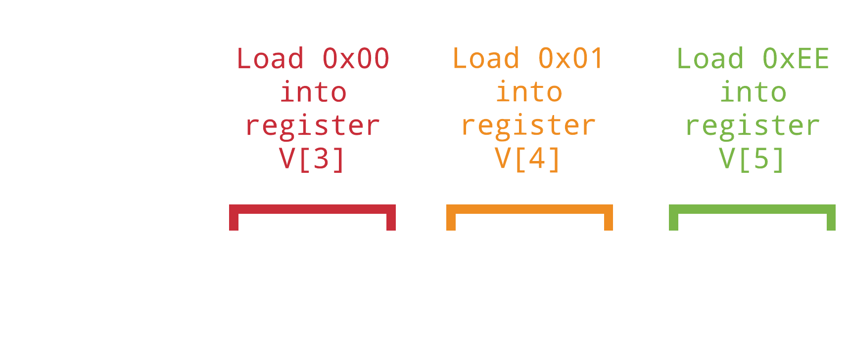
Here’s a snippet of what the CPU may read from memory.

The Stack and the Stack Pointer
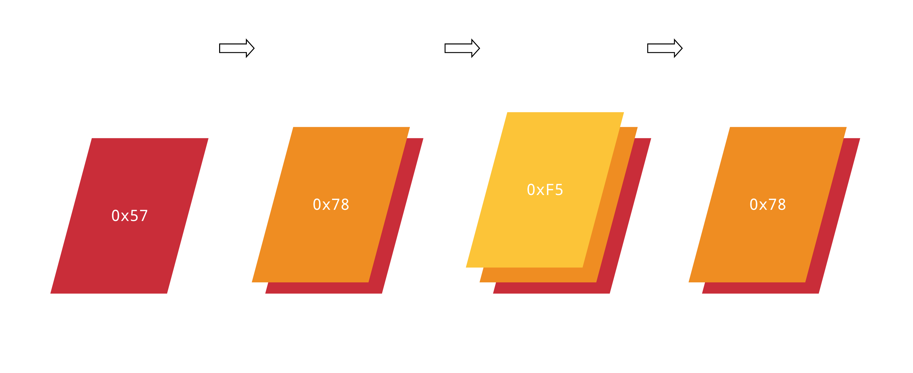
In computer science, the term stack refers to an abstract datatype serving as an array of elements. A standard stack implementation consists of two functions: Push, which adds an element to the collection of elements, and Pop, which retrieves and removes the most recently added element.
The stack pointer is responsible for recording the location of the most recently added element in the array.
Coincidentally, the functions of a stack are best represented using stacks of paper.

Similar to a stack of paper, the only element visible to the machine is located on the top of the stack.
Memory
Each system has specific chunks of memory reserved for their own functionality. Below is a memory map of the full 4KB of the CHIP-8’s memory.

As you may have noticed, the CHIP-8 contains a very simple memory layout. Most programs start at memory address 0x200, and that’s all you’ll have to worry about for the most part.
However, at the beginning of memory you may have noticed that there are 80 bytes reserved for font sprites. These sprites, which are 5 bytes each, contain graphical information for drawing hexadecimal characters 0-F. So, we know that these sprites are stored at the beginning of memory, but the question of how there are stored in memory still remains.
How are these sprites stored in memory?
Sprites are stored in memory as a series of bytes. Each byte contains enough information to draw an 8 pixel wide line, meaning the size of the sprite is determined by how many bytes make it up. A sprite made up of 1 byte will have a size of 8x1 pixels, a sprite containing 2 bytes will have a size of 8x2 pixels, and so on.
The pre-defined sprites in memory are 5 bytes long, meaning each character is 8x5 pixels. Since the CHIP-8 uses a monochrome display, pixels are either on or off, and so each bit of a byte that makes up a sprite determines which pixels are on and off on the corresponding line of 8 pixels. Below is a diagram of how the 5 bytes of the '0' character are represented in their hexadecimal, binary, and rasterized forms.
![]()
Fetch, Decode, Execute
The fetch-decode-execute cycle is arguably one of the most important things to understand when it comes to emulation development. These three instructions are the key to emulation of the CPU and therefore must be understood and implemented properly.
The CPU is simulated by fetching, decoding, and executing repeatedly, sandwiched in a while loop.
So what do each of the parts of this cycle call for, really?
Fetch
When we ask a dog to fetch a ball, it brings that ball right back to us. Unfortunately, CPUs are not dogs, and so they can’t fetch balls. So instead of asking them to fetch balls like some kind of maniac, we ask them to fetch opcodes, or instructions, from memory.
Opcodes are fetched from the memory location currently stored in the program counter. Once those opcodes are read from memory, the program counter register increments by the amount of bytes that were fetched from memory. In the case of the CHIP-8, we’d increment the program counter by 2, since each opcode is 2 bytes long.
Decode
Thanks to the CPU, we have an opcode, a single instruction, for the CPU to use. When we decode, we are telling the CPU exactly what that opcode means.
Now’s the time to bust out the CHIP-8 instruction set reference that I mentioned prior. Take a look at what the fetched opcode number corresponds to. Using this newfound knowledge, we need to guide the CPU in the right direction.
This guiding is usually done with a large switch statement, where each case ends with a function that must be executed.
Execute
The execute step pulls everything together, it’s the function at the end of the large switch statement we just mentioned. This function can do a variety of things. Again, take a look at the instruction set reference to understand exactly what this function is going to have to do.
These functions can do a variety of operations that the machine can utilize, such as:
- Loading a value into a register
- Drawing a sprite to the screen
- Clearing the screen
- Writing register values to memory
Although it may be confusing to see how these functions can be implemented, everything will begin to make sense once we begin writing code.
Until Next Time
Learning the theory behind a concept isn’t always the most interesting. It’s common for us to want to jump straight in and start writing the code. However, and especially when it comes to emulation development, having a deep understanding of what you want to implement will pay off a lot more than just diving right into programming and getting stuck halfway through because of an overlooked design choice that comes back to bite you later on.
The next post will focus primarily on implementation, so stay tuned.
Thanks for reading!